Linggo, Setyembre 12, 2010
Integral Tanks and Floor
Mark Smaalders hung around and admired his design after the "Roll the Hull" party. It must be interesting and gratifying to see your design come to life. Can you ever really imagine how sweet her lines will be?

Of course, I did manage to get a quick pic of the two guys together with their girl...

Almost every bit of lumber that had been used for the rolling frame and old strongback was used to create access to the inside of the boat.

It's on the steep side, but has a roomy landing for all the implements.

Next on the agenda was the integral water tanks.

They needed to be thoroughly glassed and sealed so that no leakage in the future would rot the hull.

Each section had a 3" baffle hole drilled and sealed to connect it to the adjacent section. This will keep the water from sloshing and shifting violently.

Two larger water tanks were created by joining the sections on each side of the keel to each other. Each section was designed to have it's own lid, set into the section of tank, making the top flush for the subfloor. Each lid needed a frame to be fitted and epoxied in for the lid to be mounted to, thus ensuring a water proof seal.


Richard's knees and feet did not appreciate the lack of flat floor. Lots of twisting and uncomfortable perching.

Blue "chalk" was used on the tank edge to see if it transferred to the frame when pressed in and would show areas needing more scribe.

Each frame over and over again.

Each was labeled and meticulously fitted.

Forward of the main saloon, a slanted floor area was prepped to become the shower sump. The small upper area is where the toilet will sit under a bench. The two small cells will be sections of bilge.

The shower pan was shaped with fillers and glass so that it would drain down to a pick up area for a sump hose that will be run through into the lower bilge area and to a manually activated pump.

A subfloor of marine ply was scribed but not yet attached. Working on a flat surface was much nicer.


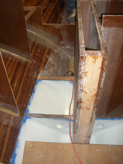
A 2-part waterbased potable tank coating (BrewCoat from Sound Coatings) was used to cover the epoxy in the tanks. There seems to be conflicting info on whether epoxy tanks are safe for storing potable water. We felt the expense of the coating was worth it, and also helped smooth out any imperfections, and help keep gremmies from growing.
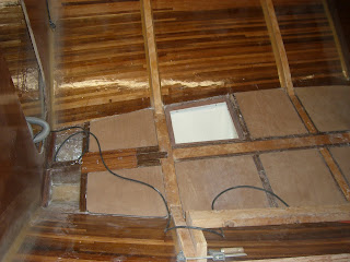
As seen in the open tank section, the frame was screwed into the hull sides and epoxied in place. Each screw could then be covered with glass and epoxy to prevent leaks. The lid would ultimately be secured to the frame with no screws or hardware exposed to the water.

A tiny limber hole at the bottom of the tank, under the baffle hole is needed to drain the water from one tank to another. There is a similar hole as high as possible up under the frame to create a vent between sections. These holes were drilled slightly oversized, filled solid with epoxy, then re-drilled through the epoxy plug. This created a water tight hole.

This view is aft from the mast. Far back is the largest bilge near the engine compartment with it's frame around it. The white tank section will have a lowered lid. This is where the bulkhead fittings for the starboard tank access will come up. The centerboard configuration created the need for creative tank access solutions.

It was decided that cleanouts/access holes to each tank section was a good idea. We didn't want to rip apart the floor at a future date to clean or maintain them, but we also worried about strength. We could not find any access covers that seemed secure and strong enough to prevent leaking under the pressure of water sloshing, so Richard designed and manufactured his own covers.

He manufactured a backer ring and a cover from a sheet of ultra high molecular weight plastic on our CNC router for each 4.5" diameter hole. Using stainless steel bolts from the inside, pre-drilled and epoxied in place, the nuts would hold the cover in place on the top side.


The little white nipple in the forward bilge is as high in the tank as possible. It will be the 1/2" air vent for the starboard tank. The flat solid area in the center is the mast step. (coin still needed)

Since there is a subfloor over the lids, hatches have to be cut in it.....and of course, a recessed area for each access cover must be cut on the router, in the exact location.

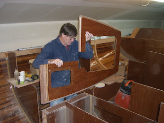
The layers of the scribing of the subfloor, due to hull shape, is obvious as Richard is showing off the fit of his hatches. To be honest, he is getting VERY sick of these tanks....
The finished subfloor for the main bilge area wraps around the centerboard.

Here is the bilge, as seen through the galley sink cabinet. Time to get off the floor and on to the joints.....
Read More..
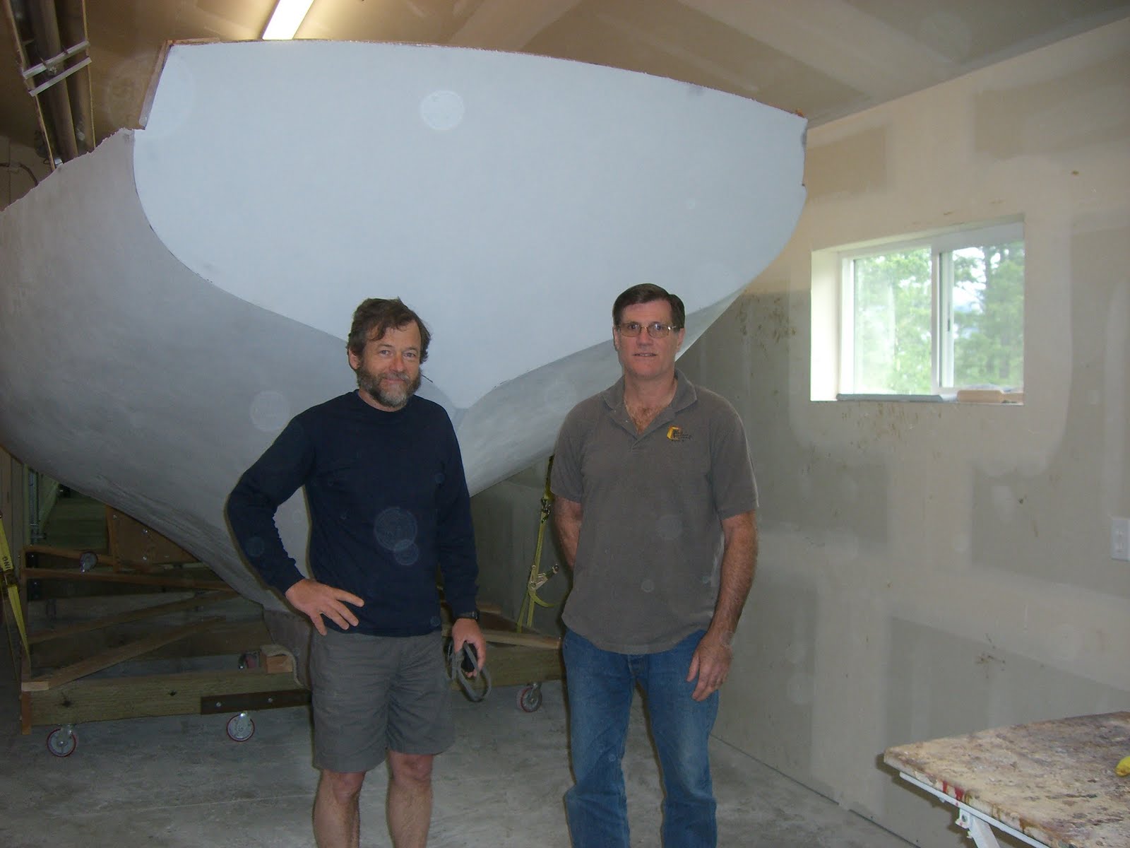
Of course, I did manage to get a quick pic of the two guys together with their girl...

Almost every bit of lumber that had been used for the rolling frame and old strongback was used to create access to the inside of the boat.

It's on the steep side, but has a roomy landing for all the implements.

Next on the agenda was the integral water tanks.

They needed to be thoroughly glassed and sealed so that no leakage in the future would rot the hull.

Each section had a 3" baffle hole drilled and sealed to connect it to the adjacent section. This will keep the water from sloshing and shifting violently.

Two larger water tanks were created by joining the sections on each side of the keel to each other. Each section was designed to have it's own lid, set into the section of tank, making the top flush for the subfloor. Each lid needed a frame to be fitted and epoxied in for the lid to be mounted to, thus ensuring a water proof seal.

A huge amount of scribing was needed to fit each frame.

Richard's knees and feet did not appreciate the lack of flat floor. Lots of twisting and uncomfortable perching.

Blue "chalk" was used on the tank edge to see if it transferred to the frame when pressed in and would show areas needing more scribe.

Each frame over and over again.

Each was labeled and meticulously fitted.

Forward of the main saloon, a slanted floor area was prepped to become the shower sump. The small upper area is where the toilet will sit under a bench. The two small cells will be sections of bilge.

The shower pan was shaped with fillers and glass so that it would drain down to a pick up area for a sump hose that will be run through into the lower bilge area and to a manually activated pump.

A subfloor of marine ply was scribed but not yet attached. Working on a flat surface was much nicer.

Starting to get a feel for space in the boat. Building a boat seems similar to building a house. There are times when it seems small, and then as more things are added it grows and seems roomier.

Underneath that subfloor, each tank was prepped for finishing. The blue tape prevented the epoxy from slopping up where the frames would be mounted. Each tank was sanded thoroughly.

A 2-part waterbased potable tank coating (BrewCoat from Sound Coatings) was used to cover the epoxy in the tanks. There seems to be conflicting info on whether epoxy tanks are safe for storing potable water. We felt the expense of the coating was worth it, and also helped smooth out any imperfections, and help keep gremmies from growing.

As seen in the open tank section, the frame was screwed into the hull sides and epoxied in place. Each screw could then be covered with glass and epoxy to prevent leaks. The lid would ultimately be secured to the frame with no screws or hardware exposed to the water.

A tiny limber hole at the bottom of the tank, under the baffle hole is needed to drain the water from one tank to another. There is a similar hole as high as possible up under the frame to create a vent between sections. These holes were drilled slightly oversized, filled solid with epoxy, then re-drilled through the epoxy plug. This created a water tight hole.

This view is aft from the mast. Far back is the largest bilge near the engine compartment with it's frame around it. The white tank section will have a lowered lid. This is where the bulkhead fittings for the starboard tank access will come up. The centerboard configuration created the need for creative tank access solutions.

It was decided that cleanouts/access holes to each tank section was a good idea. We didn't want to rip apart the floor at a future date to clean or maintain them, but we also worried about strength. We could not find any access covers that seemed secure and strong enough to prevent leaking under the pressure of water sloshing, so Richard designed and manufactured his own covers.

He manufactured a backer ring and a cover from a sheet of ultra high molecular weight plastic on our CNC router for each 4.5" diameter hole. Using stainless steel bolts from the inside, pre-drilled and epoxied in place, the nuts would hold the cover in place on the top side.

Here, the bolts are peaking through the pre-drilled holes.

The little white nipple in the forward bilge is as high in the tank as possible. It will be the 1/2" air vent for the starboard tank. The flat solid area in the center is the mast step. (coin still needed)

Since there is a subfloor over the lids, hatches have to be cut in it.....and of course, a recessed area for each access cover must be cut on the router, in the exact location.

The layers of the scribing of the subfloor, due to hull shape, is obvious as Richard is showing off the fit of his hatches. To be honest, he is getting VERY sick of these tanks....

The finished subfloor for the main bilge area wraps around the centerboard.

Here is the bilge, as seen through the galley sink cabinet. Time to get off the floor and on to the joints.....

Biyernes, Setyembre 10, 2010
Glass Work, Keel Bolts, and Sheer
The pictures sort of jump around at this point. Work on the tanks and the interior of the hull alternate and overlay during October and November.

The top of the access stairs became a staging area for all things glass and epoxy.

During drying periods while glassing the integral tanks, Richard worked on securing the existing bulkheads/ frames to the hull. They were currently only being held by the epoxy applied during the strip planking.
In the above picture you can see the fillet in the far bulkhead joint. It is beige in color, due to the wood flour and fumed silica added to the epoxy to thicken and create structural filler. The fillet gives the joint a radius and strength. The glass fabric can not make sharp corners.

The strips of biaxial fiberglass were cut with Jane's fabric rotary cutter. Cutting with scissors causes lots of fraying and frustration.


On close inspection you can see the fillet with the fabric wetted over it.

The frames were only filleted.

This shows the glassing and filleting and epoxy work while it is drying in the head area.

The cedar is pretty wetted out with a couple coats of epoxy and fillets at the frames.

View of the stem, glassed, wetted, and filleted.

Structural taping was used at places that will be covered by veneers, paint or trim.

The engine supports were reshaped to fit the chosen Beta Marine, and glassed into space. The glass on the hull is sanded smooth. The blue tape is covering and protecting the bronze rod/bolts that are drilled through the rear deadwood.

A bit of head scratching went into design and construction of the quarter berth.

Lots of fitting and scribing....

In and out the bunk goes....

This shows the final quarter berth with access holes in place.

Epoxy work in the engine compartment is completed. This will be partially under the cockpit. Side walls will frame out the remainder of the compartment.

Don Goodspeed came over to assist with drilling the keel bolt holes. They will hold the lead keel in place and it is important to get them as straight as possible.
The extra long bit is very intimidating.

A jig was created at each keel bolt site to help keep the shaft plumb during the drill.

Fingers hold the bit evenly spaced from the jig.

Not much error fore or aft would mean coming out the side of the floor frame.
The bit had to removed and cleaned several times for each hole.

There were a total of twelve holes drilled through the hull of the boat. Every one was a success!
We started playing around with cabinetry placement. This is looking forward into the head compartment. The cardboard cutout will be a bench covering the toilet in the forward storage/workshop/head area.

The starboard settee needs to be adjusted to cover the frame in the middle....

Placement and dimensions being critiqued.....poor Richard. The first-mate is particular!
To shape the sheer from the designed offsets, the sheer needed to be marked at the appropriate height above the DWL (designed waterline) at each station. The mark showing DWL remained visible under the epoxy on the main bulkhead. A ruler was clamped in place and a water level was used to find the correct placement of the sheer on the outside of the hull. The clear tubing (on left) was run out through a keel bolt hole and filled with water.

A thin batten painted flat black was clamped in place along the pencil marks.


Read More..

The top of the access stairs became a staging area for all things glass and epoxy.

During drying periods while glassing the integral tanks, Richard worked on securing the existing bulkheads/ frames to the hull. They were currently only being held by the epoxy applied during the strip planking.
In the above picture you can see the fillet in the far bulkhead joint. It is beige in color, due to the wood flour and fumed silica added to the epoxy to thicken and create structural filler. The fillet gives the joint a radius and strength. The glass fabric can not make sharp corners.

The strips of biaxial fiberglass were cut with Jane's fabric rotary cutter. Cutting with scissors causes lots of fraying and frustration.
Epoxy was mixed by the small batch and applied with cheap disposable 1" paint brushes.
The glass was applied in 3 layers.

First layer was positioned mostly on the hull, barely onto the bulkhead. The second mostly on the bulkhead, and the third equally across the filleted joint.

On close inspection you can see the fillet with the fabric wetted over it.

The frames were only filleted.

This shows the glassing and filleting and epoxy work while it is drying in the head area.

The cedar is pretty wetted out with a couple coats of epoxy and fillets at the frames.

View of the stem, glassed, wetted, and filleted.

Structural taping was used at places that will be covered by veneers, paint or trim.

The engine supports were reshaped to fit the chosen Beta Marine, and glassed into space. The glass on the hull is sanded smooth. The blue tape is covering and protecting the bronze rod/bolts that are drilled through the rear deadwood.

A bit of head scratching went into design and construction of the quarter berth.

Lots of fitting and scribing....

In and out the bunk goes....

This shows the final quarter berth with access holes in place.

Epoxy work in the engine compartment is completed. This will be partially under the cockpit. Side walls will frame out the remainder of the compartment.

Don Goodspeed came over to assist with drilling the keel bolt holes. They will hold the lead keel in place and it is important to get them as straight as possible.

The extra long bit is very intimidating.

There was worry about it being strong enough to penetrate through the floor frames and the dense deadwood. They were created with many layers of wood and epoxy.

A jig was created at each keel bolt site to help keep the shaft plumb during the drill.

Fingers hold the bit evenly spaced from the jig.

Not much error fore or aft would mean coming out the side of the floor frame.

The bit had to removed and cleaned several times for each hole.

There were a total of twelve holes drilled through the hull of the boat. Every one was a success!

We started playing around with cabinetry placement. This is looking forward into the head compartment. The cardboard cutout will be a bench covering the toilet in the forward storage/workshop/head area.

The starboard settee needs to be adjusted to cover the frame in the middle....

Placement and dimensions being critiqued.....poor Richard. The first-mate is particular!

To shape the sheer from the designed offsets, the sheer needed to be marked at the appropriate height above the DWL (designed waterline) at each station. The mark showing DWL remained visible under the epoxy on the main bulkhead. A ruler was clamped in place and a water level was used to find the correct placement of the sheer on the outside of the hull. The clear tubing (on left) was run out through a keel bolt hole and filled with water.

Here it is hanging out the bottom. The water height at the interior end was held at the right height on the ruler, and the far end was held against the outside of the hull at the correct station, and a pencil mark applied.

A thin batten painted flat black was clamped in place along the pencil marks.

This helped us in visualizing the sheer of the deck, and fairing any humps or dips.

The sheer clamp was then trimmed and the top angled to accommodate the slope of the deck.
Mag-subscribe sa:
Mga Post (Atom)