Huwebes, Abril 24, 2014
Didi 950 Hulls Taking Shape
The Didi 950 projects of Fred Grimminck in Australia and Mike Vermeersch in USA continue in parallel. Fred's build is from plans only and Mike's is from a kit that was cut by CNC router. Both have completed the flat sheet panels of the sides and bottom and are now skinning the radiused parts of their hulls. This is the stage that the hull shape really starts to show.
Some of the photos that I show of these two projects show minor differences, due to building from a pre-cut kit or with the builder cutting all components. Both produce the same boat at the end of the process but they may look a little different at times while being built.
The photo above is of Mike's kit boat, with neat edges at the sheer (where hull and deck will meet). The photo below is of Fred's boat with irregular edges at the sheer. This is because the kit panels are supplied with a uniform strip of waste to be trimmed off to the final line after turning the hull over, while the boat built without a kit has the panels inividually cut by the builder and the waste width may vary.
The radius is skinned in two layers, made with narrow transverse strips. The first layer lies on the stringers and the doublers of the tangent stringers, fitted between the edges of the side and bottom panels. These edges have rebates pre-cut into them and onto which the second layer will be laid.
Construction of the boat in Latvia has now started and the boat in Greece will soon follow. To see more of this design and others in our stock design range, please visit http://dixdesign.com.
Read More..
Some of the photos that I show of these two projects show minor differences, due to building from a pre-cut kit or with the builder cutting all components. Both produce the same boat at the end of the process but they may look a little different at times while being built.
 |
| Side and bottom panels all completed, ready for radius to start. |
 |
| Same stage, Fred's boat. Backbone still to be trimmed at forefoot. |
 |
| First layer of radius being fitted to Mike's boat. |
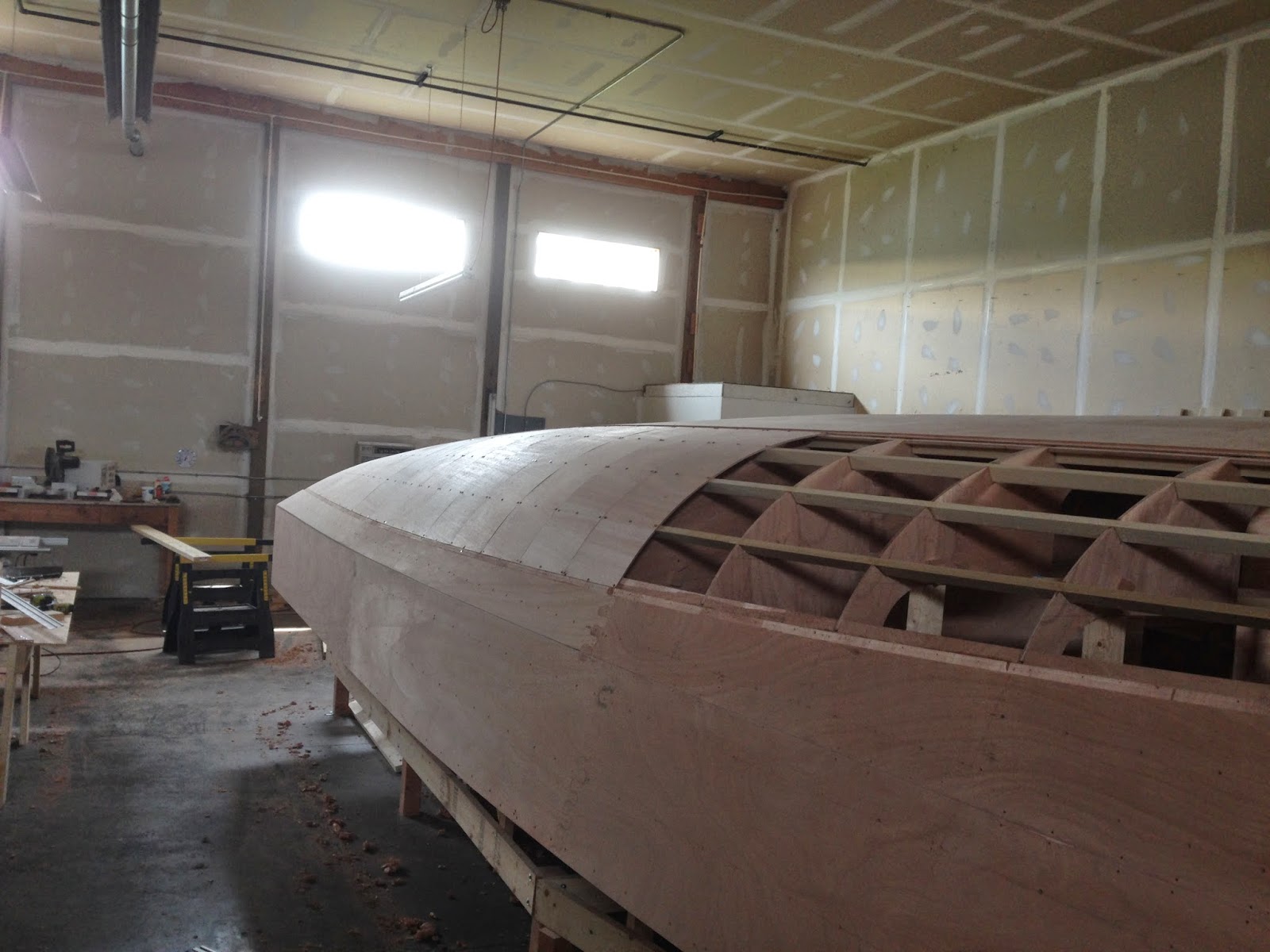 |
| The rebate along the edge of the side panel can be seen in this photo. |
 |
| Final hull shape starting to become clear. |

Lunes, Abril 7, 2014
Didi 950 Projects
There appears to be considerable interest in my posts about the boats being built to our Didi 950 design. This is a radius chine plywood design with hard chine in the topsides, designed to fit into the Classe 950 box rule. In the past few days I have received a bunch of new photos that show the build process clearly, as well as some updated progress photos.
Before going into the new photos, you might like to read the article that I posted today on my Boatbuilder Tips for Amateurs blog about how to construct building stocks or beds, the foundation off which the skeleton of a wooden boat is built. It is illustrated with photos of the Didi 950 that is being built by Fred Grimminck in Australia. The photos below are mostly of that same project, being built from scratch without a kit.
The photo below shows the various backbone components, all of which slot eggcrate-fashion into the bulkheads. The slots help to locate the bulkheads and backbones correctly relative to each other. The bow and stern have single backbone on centreline and the mid-part of the hull as two backbones that run down each side of the keel support box. The two shorter pieces on the right are the paired double-backbone parts. Next toward the left is the aft backbone, which turns up at the far end to support the transom. Extreme left is the bow backbone, which turns up at the far end to form the stem and supports a bow bulkhead into which the forward ends of the stringers are located.
The photos below show a few of the forward bulkheads with the bow backbone dry-fitted in place. The backbone has doublers just below deck level for through-bolting the bow chainplate. The doublers can be seen at the forward lower end of the backbone.
In this next photo, the transom doubler has been set up as a doubler and the stringers etc run through, then are trimmed flush. When the transom is glued over the doubler the end-grain of the longitudinals will be covered and protected. Look through the 4th cutout from left through the doubler to see how the aft end of the aft backbone turns up against the inside face of the doubler. The backbone has locating tabs that slot through the doubler, seen as light-coloured marks on centreline of the doubler. In the lower photo the transom is being glued over the outside of the doubler.
The sheer clamps on this design sit diagonally across the corner at the intersection between hull sides and decks. They are screwed and glued to cleats on the faces of all bulkheads. In this photo the sheer clamp is clamped to those cleats. You can also see how the stringers are slotted through the bulkheads. Once the hull skin has been glued on, these junctions become very strong and rigid
Looking forward along the hull just prior to fitting the bottom skin. The wide stringers on both sides are the tangent stringers, with doublers to back up the joint between flat bottom panels and radius skin panels at the turn of the bilge. The single aft backbone can be seen running through to the 3rd bulkhead from the bottom of the photo. The double backbone runs forward from the 2nd bulkhead from the bottom of the photo, then changes back to a single backbone further forward, also visible.
Stringers in the forward part of the hull, mainly showing the radius area. The two broad stringers are at the tangents, joining the flat and radiused skins together. Between them are three radius stringers, over which the double-skin radius will be formed. Below the lower of the two tangent stringers are the stringers for the side skin panels.
This last photo shows Mike Vermeesch's boat, being built from a kit in Ohio. Mike has the side panels all dry-fitted to check for fit ahead of gluing in place. Looks like a nice fit. The bow will be capped with solid wood, which will cover and protect the end-grain of the stringers.
Thank you to both Fred Grimminck and Mike Vermeersch for taking the trouble to send me these photos and allowing their use.
To see our other designs, please visit http://dixdesign.com/ .
Read More..
Before going into the new photos, you might like to read the article that I posted today on my Boatbuilder Tips for Amateurs blog about how to construct building stocks or beds, the foundation off which the skeleton of a wooden boat is built. It is illustrated with photos of the Didi 950 that is being built by Fred Grimminck in Australia. The photos below are mostly of that same project, being built from scratch without a kit.
The photo below shows the various backbone components, all of which slot eggcrate-fashion into the bulkheads. The slots help to locate the bulkheads and backbones correctly relative to each other. The bow and stern have single backbone on centreline and the mid-part of the hull as two backbones that run down each side of the keel support box. The two shorter pieces on the right are the paired double-backbone parts. Next toward the left is the aft backbone, which turns up at the far end to support the transom. Extreme left is the bow backbone, which turns up at the far end to form the stem and supports a bow bulkhead into which the forward ends of the stringers are located.
 |
| Didi 950 backbone components. Click on all photos to enlarge. |
 |
| Didi 950 bow backbone and forward bulkheads |
 |
| Didi 950 bulkheads and backbones |
 |
| Didi 950 transom doubler |
 |
| Didi 950 transom being glued over doubler. |
 |
| Didi 950 sheer clamp |
 |
| Didi 950 bottom stringers and backbones |
 |
| Didi 950 stringers |
 |
| Didi 950 hull side panels |
To see our other designs, please visit http://dixdesign.com/ .
Sabado, Abril 5, 2014
Didi 950 in Australia
Fred Grimminck in Queensland, Australia, has previously built a boat to our Didi Mini design. Now he is building a Didi 950. In contrast to the boat of Mike Vermeersch that I showed yesterday, Fred is building his boat from scratch, marking and cutting the plywood panels himself from our drawings.
Today I have received photos from Fred of his project. He is at the same stage as Mike but the different perspective of his photos shows the details from different angles to help visualise how it all goes together. Click on the photos to enlarge.
In this photo you can see how the bottom panels are slightly Veed aft but the V increases toward the bow and the flat panels become very fine, both features to soften the ride when the boat is planing fast in lumpy water and slamming over short waves can become uncomfortable. The edges of the panels land on the doublers of the tangent stringers at the intersections of flat and radiused skin panels. The edges are rebated to half-thickness, with the first layer of radius plywood landing on the doubler and the second layer landing on the rebate, forming a Z-shape joint detail.
In the photo above, the doubler at the upper tangent is in place and part of the lower side panel is clamped in place, seen at bottom right. The left edge of this panel has been planed to form the sloping surface for the scarph joint to the next piece, the main difference from the jigsaw joints of Mike's kit. Also visible in this photo, are scarph joints in some of the stringers. These appear to have been glued in place on the hull. The alternative is to pre-glue them into long lengths before installing in the boat.
The photo above shows some of the interior detail. The transom is 9mm plywood but has doublers to strengthen it around the perimeter, at the backbone and at the rudder hardware. You can see the plywood backbone passing through the bulkhead ahead of the transom. These intersections are self-locating egg-crate detailing to assist with accuracy during setting up the skeleton. The backbone is on centreline in bow and stern but changes to a pair of backbones offset from centreline from forward of the mast through to the cockpit.
A major difference between the two boats of Mike and Fred is in the keel detailing. Mikes boat has a fixed bulb keel that hangs from an internal support box that is bolted between the two components of the double backbone. The support box also holds the engine beds and bearers, sited directly over the keel. Fred's boat will have a lifting keel. It will be housed in a modified keel support box of identical footprint but with integrated casing for the lifting keel and without the engine beds. Fred's engine will be a saildrive unit located under the companionway and front of the cockpit.
There are also boats to the Didi 950 design beign built in Greece and Latvia. Watch this blog for news on all of them.
Go to http://dixdesign.com/ to see our full range of designs.
Read More..
Today I have received photos from Fred of his project. He is at the same stage as Mike but the different perspective of his photos shows the details from different angles to help visualise how it all goes together. Click on the photos to enlarge.
 |
| Bottom panels fitted, bow view |
 |
| Ready for side panels to start |
 |
| Interior view of transom and cockpit area |
A major difference between the two boats of Mike and Fred is in the keel detailing. Mikes boat has a fixed bulb keel that hangs from an internal support box that is bolted between the two components of the double backbone. The support box also holds the engine beds and bearers, sited directly over the keel. Fred's boat will have a lifting keel. It will be housed in a modified keel support box of identical footprint but with integrated casing for the lifting keel and without the engine beds. Fred's engine will be a saildrive unit located under the companionway and front of the cockpit.
There are also boats to the Didi 950 design beign built in Greece and Latvia. Watch this blog for news on all of them.
Go to http://dixdesign.com/ to see our full range of designs.
Biyernes, Abril 4, 2014
Didi 950 Build - Bottom Skin Panels
Mike Vermeersch's amateur boatbuilding project of a Didi 950 is moving on to the next stage, with bottom panels fitted and work starting on the side panels. Mike is building from a plywood kit that we supplied to him and reports that the fit is good. The kit has jigsaw joints on all large panels, making them easy to assemble either on the floor or on the boat.
Two of the stringers each side, at the junctions between flat and radiused skin areas, have plywood doublers attached to serve as backing pads to the joint. I call these the tangent stringers. The doubler on the upper tangent stringer is in process of being fitted and can be seen running forward from the transom through to the third bulkhead from aft.
In the photo below, the transom has been fitted, followed by the bottom panels. These panels each have two transverse jigsaw joints and join each other at a centreline butt joint over the plywood backbone. In the photo the jigsaw joints have temporary battens over them to secure them while the glue is setting.
Mike has also started to dry-fit the side panels ahead of gluing in place. At the right of the photo the forward lower panel can be seen and which will continue through to the transom. The lower edge, as seen upside-down like this, forms one half of the chine. The other half of the chine will be formed by the upper side panel.
Today Mike's 300lb brother decided to test the hull stiffness of this partially-built Didi 950 . He climbed onto the bottom of the boat and jumped on the bottom panels. They passed his improvised test but I think that I would have recommended that he wait until the whole hull was skinned before doing such a test.
The broad stringer that shows on this photo is the upper tangent that will join the lower side panel to the radius.
To see our other designs, visit http://dixdesign.com/ .
Read More..
 |
| Didi 950 with all stringers installed. |
In the photo below, the transom has been fitted, followed by the bottom panels. These panels each have two transverse jigsaw joints and join each other at a centreline butt joint over the plywood backbone. In the photo the jigsaw joints have temporary battens over them to secure them while the glue is setting.
 |
| Bottom panels fitted. |
Today Mike's 300lb brother decided to test the hull stiffness of this partially-built Didi 950 . He climbed onto the bottom of the boat and jumped on the bottom panels. They passed his improvised test but I think that I would have recommended that he wait until the whole hull was skinned before doing such a test.
 |
| Mike's 300lb brother tests the Didi 950 hull stiffness. |
To see our other designs, visit http://dixdesign.com/ .
Lunes, Marso 24, 2014
More on Stability with Water Ballast
John Gilbert asked a question in response to my recent post, Stability with Water Ballast.
I do not get why the red and blue curves do not meet up at 180 degrees. Inverted the boat has no windward side as you point out, so you have water ballast on one side and none on the other side. As you have drawn the curves you have powerful stability in the inverted position with the water on one side (red), but actually a righting moment if you have water on the other side(blue). What is the difference?
To help with understanding this I thought it better to write a new post that expands on the dynamics of stability than to try to answer it in the comments section after that post.
This will be more easily understood by seeing a diagram showing the stability graph expanded through a full 360 degrees rather than all conditions overlaid on top of each other in a 0-180 degree range. This is exactly the same stability info for the Didi 950 as shown in the graph of my earlier post but shown in a different manner.
I will start with the green curve. This shows the stability without water ballast. The centre of gravity (CG) is on centreline. The stability curve intersects with the horizontal grid line at 0 degrees heel and increases identically both to left and right of the 0 degree line, so the boat will float without any heel to either side when right way up. The boat will stay that way in the absence of any wind, wave action or crew movement on the boat.
Follow the green curve until it comes down past 130 degrees to again intersect with the horizontal line at the Angle of Vanishing Stability (AVS). Then it enters a range of negative stability where it will proceed toward upside-down. At 170 degrees it crosses to above the horizontal line again. This indicates that the superstructure volume is trying to turn it back upright and doesn't want the boat to lie totally inverted. It will easily flop back and forth between the 170 and 190 degree points. The boat can return to upright along either green curve.
This all depends on a totally waterproof superstructure, of course. In practice water is likely to enter the boat at a rate that depends on what is open at the time, which will affect the inverted stability.
Moving on to the stability with water ballast, in my earlier post I said that the boat will capsize along the red curve and recover along the blue curve. I explained the relationship between the two curves but that relationship is not easy to visualise if only seen across the 180 degree range.
In the diagram above you can see that the red and blue curves only meet in two places and both are on the horizontal line. These are the two points at which the boat will rest when there are no outside influences from wind, waves or crew movement.
The boat cannot rest totally upright nor totally upside-down because the weight of the water to one side is heeling it toward that side. It will rest at approximately -5 degrees heel instead of upright and at 200 degrees instead of upside-down when inverted.
Bearing in mind that the areas of the curves below the horizontal line indicate how much energy it needs for the boat to get past the AVS points so that it can right itself when in that 200 degree situation, it is now easy to see that it will take a large amount of wave energy to get past the AVS of the red curve but a very small amount of wave action to get past the AVS of the blue curve.
This graphic shows that if a water ballasted boat capsizes it will do so along the red curve but it is very unlikely to return along that same path, nor is it likely to stay capsized for long. Once past the AVS of the red curve the negative stability will push it to 20 degrees past upside-down. After that the blue curve will take over and almost guarantee that the boat returns to right-way-up pronto.
Read More..
I do not get why the red and blue curves do not meet up at 180 degrees. Inverted the boat has no windward side as you point out, so you have water ballast on one side and none on the other side. As you have drawn the curves you have powerful stability in the inverted position with the water on one side (red), but actually a righting moment if you have water on the other side(blue). What is the difference?
To help with understanding this I thought it better to write a new post that expands on the dynamics of stability than to try to answer it in the comments section after that post.
This will be more easily understood by seeing a diagram showing the stability graph expanded through a full 360 degrees rather than all conditions overlaid on top of each other in a 0-180 degree range. This is exactly the same stability info for the Didi 950 as shown in the graph of my earlier post but shown in a different manner.
 |
| Diagram of Stability through 360 Degrees |
Follow the green curve until it comes down past 130 degrees to again intersect with the horizontal line at the Angle of Vanishing Stability (AVS). Then it enters a range of negative stability where it will proceed toward upside-down. At 170 degrees it crosses to above the horizontal line again. This indicates that the superstructure volume is trying to turn it back upright and doesn't want the boat to lie totally inverted. It will easily flop back and forth between the 170 and 190 degree points. The boat can return to upright along either green curve.
This all depends on a totally waterproof superstructure, of course. In practice water is likely to enter the boat at a rate that depends on what is open at the time, which will affect the inverted stability.
Moving on to the stability with water ballast, in my earlier post I said that the boat will capsize along the red curve and recover along the blue curve. I explained the relationship between the two curves but that relationship is not easy to visualise if only seen across the 180 degree range.
In the diagram above you can see that the red and blue curves only meet in two places and both are on the horizontal line. These are the two points at which the boat will rest when there are no outside influences from wind, waves or crew movement.
The boat cannot rest totally upright nor totally upside-down because the weight of the water to one side is heeling it toward that side. It will rest at approximately -5 degrees heel instead of upright and at 200 degrees instead of upside-down when inverted.
Bearing in mind that the areas of the curves below the horizontal line indicate how much energy it needs for the boat to get past the AVS points so that it can right itself when in that 200 degree situation, it is now easy to see that it will take a large amount of wave energy to get past the AVS of the red curve but a very small amount of wave action to get past the AVS of the blue curve.
This graphic shows that if a water ballasted boat capsizes it will do so along the red curve but it is very unlikely to return along that same path, nor is it likely to stay capsized for long. Once past the AVS of the red curve the negative stability will push it to 20 degrees past upside-down. After that the blue curve will take over and almost guarantee that the boat returns to right-way-up pronto.
Miyerkules, Marso 5, 2014
It's My Boat Radio Interview
It's My Boat Radio is a weekly online radio program that runs on Blog Talk Radio. Hosts are Barbara Jean Walsh and Ann Avary. They do interviews with people who are experienced boaters or in the boating industry, on a broadening range of subjects.
This week I was invited to participate, on the subject of kit boats. You can listen in to the program by clicking on the link below. It is about 30 minutes and you can listen while doing other stuff. Unlike live radio, if you think that you missed something then you can go back to whatever part you missed and listen again, or go back to the start and listen to the whole program again.
Kit Boats and More! online radio program
Plywood kits for our designs
To see our full range of designs, go to http://dixdesign.com/
Read More..
This week I was invited to participate, on the subject of kit boats. You can listen in to the program by clicking on the link below. It is about 30 minutes and you can listen while doing other stuff. Unlike live radio, if you think that you missed something then you can go back to whatever part you missed and listen again, or go back to the start and listen to the whole program again.
Kit Boats and More! online radio program
 |
| Small selection of our plywood kit designs |
To see our full range of designs, go to http://dixdesign.com/
Huwebes, Pebrero 27, 2014
Stability with Water Ballast
A potential builder of the Didi 950 asked me a question about stability with water ballast. He could not find an explanation on the Internet describing the effects of water ballast on a boat when capsized, so here it is.
After looking at the stability curve, he was concerned that the stability curve with water ballast to windward, the normal position for sailing in strong winds, has a very large area of negative stability. He wanted to know how that affects the time that the boat will take to right itself if capsized. This is a natural question following the amount of discussion that has been happening after our recent capsize in the Didi 38 "Black Cat" and the very rapid manner in which she returned to upright.
Shown below is the stability graph of the Didi 950 in fully loaded condition; click on the diagram to enlarge it. This is the condition of lowest stability due to the inclusion of crew, stores, liquids and many other weights that are above the centre of gravity (CG) of the boat. There are three curves shown. When looking at the graph, consider that the area enclosed by each curve above the horizontal 0 line is a measure of the energy that is required to take the boat from upright to the point of vanishing stability (AVS) where the curve crosses the 0 line. Until the AVS is reached, the boat will return to upright if no additional heeling force is applied to it. Beyond the AVS the boat will continue to full capsize unless there is another force being applied that will return it to the positive side of the AVS.
The green curve is with ballast tanks empty, so akin to sailing a boat that has no water ballast. This curve is very similar in form to that of "Black Cat", with the area enclosed by the curve above the 0 line many times greater than the area enclosed by the curve below the 0 line. She would right herself very quickly with no water ballast. The red curve is with the windward ballast tanks filled, good for powering to windward or power-reaching in strong conditions. The blue curve is with the leeward ballast tanks filled. One would not sail her like this but it is a situation that could result from an accidental gybe in strong winds.
With no wind or waves and the ballast tanks on one side filled, the boat will not rest upright. It will heel over until it stabilises at a heel angle that places the CG vertically in line with the centre of buoyancy (CB). That will be the nearest crossing of the curve with the 0 line, which is at 5 degrees in this case, seen on the blue curve. Add some wind to bring the boat to 0 degrees heel and the righting moment that is working is the point where the red curve hits the left edge of the graph. Without water ballast the boat must heel to 6 degrees to reach the same righting moment. That is where the power benefit is coming from with water ballast, the boat will sail more upright than with empty tanks, in the same wind strength.
Note that all three curves are closely bunched when the boat is heeled 90 degrees. This is a knock-down situation, probably from losing control when driving hard downwind under spinnaker. The mast is horizontal but not in the water. This bunching of the curves at 90 degrees is because of the position of the ballast tanks in this design, low in the boat fairly close to the vertical CG. There would be a bigger spread if the tanks were located high up under the deck.
The red curve shows the benefit of increased righting moment when the windward tank is filled. There is considerably greater gain in stability shown by the red curve than lost stability, shown by the blue curve, when ballast is on the wrong side.
Read More..
After looking at the stability curve, he was concerned that the stability curve with water ballast to windward, the normal position for sailing in strong winds, has a very large area of negative stability. He wanted to know how that affects the time that the boat will take to right itself if capsized. This is a natural question following the amount of discussion that has been happening after our recent capsize in the Didi 38 "Black Cat" and the very rapid manner in which she returned to upright.
Shown below is the stability graph of the Didi 950 in fully loaded condition; click on the diagram to enlarge it. This is the condition of lowest stability due to the inclusion of crew, stores, liquids and many other weights that are above the centre of gravity (CG) of the boat. There are three curves shown. When looking at the graph, consider that the area enclosed by each curve above the horizontal 0 line is a measure of the energy that is required to take the boat from upright to the point of vanishing stability (AVS) where the curve crosses the 0 line. Until the AVS is reached, the boat will return to upright if no additional heeling force is applied to it. Beyond the AVS the boat will continue to full capsize unless there is another force being applied that will return it to the positive side of the AVS.
The green curve is with ballast tanks empty, so akin to sailing a boat that has no water ballast. This curve is very similar in form to that of "Black Cat", with the area enclosed by the curve above the 0 line many times greater than the area enclosed by the curve below the 0 line. She would right herself very quickly with no water ballast. The red curve is with the windward ballast tanks filled, good for powering to windward or power-reaching in strong conditions. The blue curve is with the leeward ballast tanks filled. One would not sail her like this but it is a situation that could result from an accidental gybe in strong winds.
 |
| Didi 950 Stability Graph. Click to enlarge. |
Note that all three curves are closely bunched when the boat is heeled 90 degrees. This is a knock-down situation, probably from losing control when driving hard downwind under spinnaker. The mast is horizontal but not in the water. This bunching of the curves at 90 degrees is because of the position of the ballast tanks in this design, low in the boat fairly close to the vertical CG. There would be a bigger spread if the tanks were located high up under the deck.
The red curve shows the benefit of increased righting moment when the windward tank is filled. There is considerably greater gain in stability shown by the red curve than lost stability, shown by the blue curve, when ballast is on the wrong side.
All three curves show that the wind alone can't capsize the boat. When the mast hits the water there is still considerable righting moment available for all three situations. If the boat is in large waves and hit by a big one while knocked flat, the added energy from the wave can capsize the boat in all three situations.
It seems counter-intuitive but the condition most likely to invert the boat under wave action after a knock-down is with the water ballast to windward (red), i.e. the condition in which the boat will be sailed in strong winds. This is because after the water ballast passes beyond the point where it is vertically above the overall CG of the boat that extra weight is on the wrong side of the CG and is helping to capsize the boat rather than to bring it back to upright. It pulls the red curve below the green curve and reduces the AVS from 133 degrees to 122 degrees.
Overall it takes more energy to capsize the boat from upright with water ballast than without, evaluated by comparing the area enclosed by the red curve with the area enclosed by the green curve. When the area enclosed by the blue curve is compared with the green curve, there is very little difference. It will take a similar amount of energy to capsize the boat without water ballast and with water ballast on the wrong side, when going from upright. Ironically, the wrong side has the greatest amount of reserve stability after a knock-down and has the greatest angle of AVS, so it is the condition least likely to capsize after a knock-down.
Back to our capsizing boat. Once past 122 degrees it is into a big range of negative stability that shows as the area enclosed by the red curve below the 0 line, taking it all the way to 180 degrees, i.e. totally upside-down. But see that the curve does not return to 0 at 180 degrees, which means that it is unstable at that angle. Same as happens when the boat is upright, the water ballast off to one side prevents the boat from resting at the 180 degree position. It has to rotate to where the CG is vertically aligned with the inverted CB. That is at the point where the curve crosses the 0 line. If the red curve is extended to the zero line it will be to the same angle that the blue curve crosses, i.e. 160 degrees.
It seems counter-intuitive but the condition most likely to invert the boat under wave action after a knock-down is with the water ballast to windward (red), i.e. the condition in which the boat will be sailed in strong winds. This is because after the water ballast passes beyond the point where it is vertically above the overall CG of the boat that extra weight is on the wrong side of the CG and is helping to capsize the boat rather than to bring it back to upright. It pulls the red curve below the green curve and reduces the AVS from 133 degrees to 122 degrees.
Overall it takes more energy to capsize the boat from upright with water ballast than without, evaluated by comparing the area enclosed by the red curve with the area enclosed by the green curve. When the area enclosed by the blue curve is compared with the green curve, there is very little difference. It will take a similar amount of energy to capsize the boat without water ballast and with water ballast on the wrong side, when going from upright. Ironically, the wrong side has the greatest amount of reserve stability after a knock-down and has the greatest angle of AVS, so it is the condition least likely to capsize after a knock-down.
Back to our capsizing boat. Once past 122 degrees it is into a big range of negative stability that shows as the area enclosed by the red curve below the 0 line, taking it all the way to 180 degrees, i.e. totally upside-down. But see that the curve does not return to 0 at 180 degrees, which means that it is unstable at that angle. Same as happens when the boat is upright, the water ballast off to one side prevents the boat from resting at the 180 degree position. It has to rotate to where the CG is vertically aligned with the inverted CB. That is at the point where the curve crosses the 0 line. If the red curve is extended to the zero line it will be to the same angle that the blue curve crosses, i.e. 160 degrees.
There is no windward or leeward when the boat is upside-down, the sails are under water. The boat is stable in the 160 degree position, so leaning 20 degrees to one side of upside-down. It needs to get past the nearest zero crossing to come back to upright. The boat doesn't care which way it goes. It needs a lot of energy to go back the way that it came along the red curve but very little energy to get to the 140 degree AVS crossing of the blue curve. With the motion from just a small wave it will continue past that 140 degree point. Once that point is passed, the righting moment of the blue curve takes control and will return her to upright. If the rig is still standing then the sails will fill and she will be back into the stability situation shown by the red curve. She has capsized along the red curve and righted herself along the blue curve.
In essence, it will take a lot less energy for the boat to right itself with water ballast than without, so she should right herself more quickly with the water ballast. The difference is that without water ballast she can go either way from inverted to upright but with water ballast she has to go full circle.
To visit our website, go to http://dixdesign.com/
To visit our website, go to http://dixdesign.com/
Mag-subscribe sa:
Mga Post (Atom)